

Just like a car needs to meet specific criteria, a hydraulic actuator must satisfy mechanical, hydraulic, and operational requirements, starting with torque, speed, and inertia. Whether you choose spontaneously or carefully define the requirements first is of essential importance in the design of a hydraulic drive. My message is: start by defining the technical requirements that an actuator (hydraulic motor or cylinder) must meet.
The common mistake
Suppose we need to design a rotary drive. What often happens is that people focus solely on the maximum torque and maximum speed that must be delivered. But how do we achieve that maximum torque? A car needs enough power to accelerate. In the same way, a hydraulic motor needs torque to overcome inertia. And this goes both ways. In addition to the desired static torque-and any friction torque-we must also consider the acceleration to the desired speed, or in some cases, the deceleration torque required to bring the system to a stop. After all, what is the mass of the system connected to the drive motor, and what acceleration or start-up time is required to reach the desired speed?
To determine the driving torque (T) needed for acceleration or deceleration, we use the following formula:
Tdyn ≈ J · Δn / (9.55 · Δt)
Where:
Tdyn = dynamic driving torque for acceleration or deceleration (in Newtonmeter, Nm)
J = inertia (in kg.m2)
Δn = difference in speed (nend – nstart in rpm)
Δt = acceleration of decelleration time (in seconds)
Okay, but how do I determine the value for inertia? I’ll give a few highly simplified examples.

To accelerate the load, the motor needs extra torque to overcome inertia. In the above formula J is the inertia of the system—the resistance to changes in motion. For a winch, it’s the mass of the load times the drum radius squared (J = m·r²). Example: For a winch lifting a 1,000 kg load with a drum radius of 0.5 m:
Jdyn = 1,000 kg · (0.5 m)² = 250 kg·m²
This inertia value is critical for calculating the torque needed to accelerate or decelerate the system. Ignore it, and your motor may fail to start the load or stop it safely.
In many situations, a gearbox is also installed between the hydraulic motor and the driven load. As a result, the motor torque decreases due to the static torque, but the required speed of the hydraulic motor increases. For the dynamic torque—used to accelerate and decelerate the load—the hydraulic motor torque, however, becomes many times smaller.
The calculated moment of inertia J from the previous formula, due to the gear ratio i, is now:
Jred = J / i²
Where: Jred = reduced inertia (in kg·m²)
i = gear ratio
Suppose there is a gear ratio in a 2-stage gearbox with a value of 49 for i. We then obtain the following value for the dynamic torque Tdyn:
Tdyn ≈ J · Δn /(i² × 9.55 × Δt) ≈ J · Δn /(22,930 × Δt)
So far, we’ve only considered the mechanical requirements for the drive system. What installation options are available? How much space is available for a drive motor? Or would it be better to use a gearbox that allows us to adjust the torque and speed of the drive motor? Be sure to also specify what the drive motor must do when at a standstill: does the drive need to be completely locked in this position, or is an additional brake necessary? Consider the winch drive, for example: we can incorporate a counterbalance valve into the hydraulic circuit that blocks the flow from the hydraulic motor, but the hydraulic motor itself will always start to wobble slowly under load due to internal leakage.
Case study: the winch that almost caused a disaster
Now let’s see what happens when these principles are ignored in a real system as I don’t want to withhold the following piece of practical experience from you.
What went wrong?
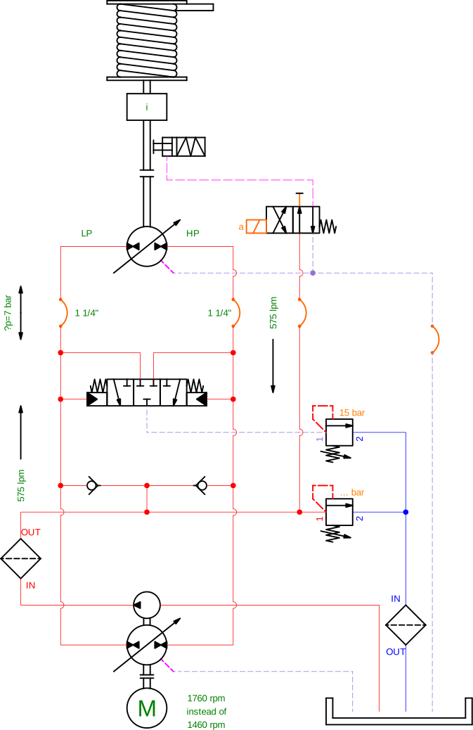
This case involves a lifting winch driven by a fast hydraulic motor, a gearbox, and a closed-loop system. For this drive mechanism the pressure for the booster valve was set to 15 bar. The hydraulic motor reaches speeds of approximately 2.100 rpm.

The pipe work from the variable pump to the hydraulic motor has been carried out with hydraulic hoses. A large volume flow of approximately 575 lpm is generated through the main pipes from the pump to the motor when the winch is released. A pressure drop of 8 bar developed from the pump to the motor because the diameter for the pipe work was designed too tightly. A hose diameter of 1 ½ “ was specified during the design of the installation. Because this type of hose was not immediately available during the build phase, personnel concerned decided there and then to fit a 1 ¼ “ hose. Also the electric motors were running at 60 Hz, so at 1760 rpm, instead of the design speed of 1460 rpm at 50 Hz. This meant that an inlet pressure of only 15-8 = 7 bar remained when the winch reached its maximum release speed. At the maximum number of 2.100 rpm for the hydraulic motor the inlet pressure of 7 bar is absolutely insufficient to prevent cavitation on the inlet side of the motor.
The result was complete cavitation, the formation of vapor bubbles in the hydraulic oil due to low pressure on the motor’s suction side. This meant that the torque characteristics of the hydraulic motor were completely lost. At that moment there was a test load of 150 mTon in the winch’s hook, which came down in a free fall movement. The free fall was stopped by the quick activation of the emergency brake, thus preventing a serious accident. Great mechanical damage was caused to the hydraulic motor and the disc brake however. The hydraulic motor completely exploded as a result of the extremely high number of rpm that was reached for a short period of time.

Root cause analysis
The failure wasn’t due to a single mistake but a chain of oversights in the design and installation phases. The boost pressure (15 bar) was insufficient for the suction side of the motor during release, especially with the actual operating conditions (higher speed, smaller hoses). Using 1¼” hoses instead of 1½” introduced a critical pressure drop, starving the motor of inlet pressure. Running the electric motors at 60 Hz instead of 50 Hz increased the flow rate, exacerbating the pressure drop. The system was not tested under real-world conditions (temperature, oil viscosity, actual motor speeds) before operation. This case underscores why defining all technical requirements upfront is non-negotiable in hydraulic system design. Here are the key takeaways to prevent similar failures:
Boost pressure is critical for the suction side:
In a lifting winch, the low-pressure (suction) side of the motor becomes the high-pressure side during release (when the load is lowering).
Always ensure sufficient boost pressure to prevent cavitation, especially at maximum speed and load. Validate boost pressure under real operating temperatures and oil viscosity—not just theoretical conditions.
Hose and Pipe Sizing Matters:
Undersized hoses or pipes cause excessive pressure drops, which can starve the motor of inlet pressure. Rule of thumb: If the pressure drop exceeds 3-5% of the system pressure, increase the hose diameter.
Verify all operating conditions:
Motor speed (Hz/rpm), flow rate, and pressure must match the design specifications. Running electric motors at 60 Hz instead of 50 Hz can increase flow rate by 20%, leading to unexpected pressure drops.
Design for the worst case:
Maximum speed + maximum load = highest risk of cavitation. Test the system at these extremes before deployment.
Redundancy saves lives (but isn’t a substitute for good design):
The emergency brake prevented a fatal accident, but proper design should have made it unnecessary. The hose diameters were increased to 1½”, and an extra boost pipe was added directly from the boost pump to the motor’s low-pressure side.
Final thought
Just as you wouldn’t buy a car without checking its towing capacity or safety features, you cannot design a hydraulic system by focusing only on torque and speed. Inertia, boost pressure, hose sizing, and operational conditions must be part of the first conversation, not an afterthought.


